Architecture Primer#
Understanding the Dial Plan Model requires a basic understanding of the architecture and the interaction between the elements. The architecture consists of three discrete layers:
Aggregation layer
Infrastructure layer
Customer-premises layer
These layers comprise the majority of the call flow interactions.
The aggregation layer handles inbound/outbound call routing between customer premises and PSTN, while all intra-customer interactions are handled at the infrastructure layers.
The numbering plan facilitates this design, allowing for a simple routing methodology, and is discussed in this section.
Aggregation Layer
Customer Premises Layer
VoiceMail - Cisco Unity Connection
Aggregation Layer#
The aggregation layer is responsible for the following:
E.164 call routing
Routing E.164 calls between two VOSS Automate customers
Routing calls from the PSTN to IP Lines on Cisco Unified Communications Manager (CUCM) clusters
Routing calls from IP Lines (on CUCM clusters) to centralized PSTN breakout
Routing calls to other components within the aggregation layer
Routing calls to Cisco WebEx (can be a separate route)
Routing calls to Cisco Contact Center Enterprise (can be a separate route)
The primary use of the aggregation is to aggregate central PSTN traffic. Any call that is received at the aggregation layer must be treated as a call either from or to the PSTN. The aggregation supports PSTN breakout like SS7 and SIP.
A service provider using an early version of VOSS Automate (VOSS-4-UC v10.x/11.5(x)) can only use the customer’s own aggregation device (third party).
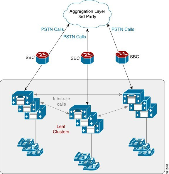
The aggregation layer is connected to the UC applications through the third-party session border controller as shown in the following figure. The SBC is used mainly as a media aggregation point. The SBC is used for media anchoring and VRF translation functions. Additionally, it provides SIP header normalization functions for inter-operating with various service provider networks. The SBC is configured manually; it is not provisioned automatically from VOSS Automate. For signaling, there is one-to-one mapping of trunk from leaf clusters to signaling aggregation node, IMS or any other third-party softswitch. In general, there is no dial plan requirement for the SBC.
Figure 1. Logical Diagram Showing SBC Adjacency for Each Customer

Note
The Forced On-Net feature in CUCM can be used between users of a customer; that is, a user dialing the PSTN number of another user of the same customer.
Calls between various clusters and the aggregation traverse SIP trunks. SIP is the only protocol that must be configured for these types of trunks.
Customer Premises Layer#
This layer connects customer endpoints: phones, mobile devices, and local gateways to the SP network; and provides end user interfaces to network management software. This layer may handle PSTN routing and Survivable Remote Site Telephony (SRST) if a local breakout design is used. This layer can also include C-series servers for UC applications as part of the Extender deployment model.
VoiceMail - Cisco Unity Connection#
Cisco Unity Connection (CUC) is connected to the leaf clusters as a SIP connection (telephony integration). For each Cisco Unified IP Phone line that exists on the leaf cluster that requires voicemail, there is also a voice mailbox definition on the CUC. On CUC, the voice mailbox definition is associated to the telephony integration and leaf cluster that contains the line definition. The leaf clusters have a voicemail Pilot Number defined that helps to route calls to the CUC. With this scenario, each leaf cluster can use the same number for the voicemail pilot number.
Note
For Shared Architecture Dial Plan (G3) dial plan, the voicemail pilot number can be shared within a customer (that is, across locations) but it has to be unique across customers that belong to the shared architecture of CUCM and CUC.
